Background
Lift pin alignment in the Metal Deposition chambers had previously been checked visually. The goal of the project was to standardize that inspection with an automated pass/fail system and create a traceable record for each inspection.
Mechanical
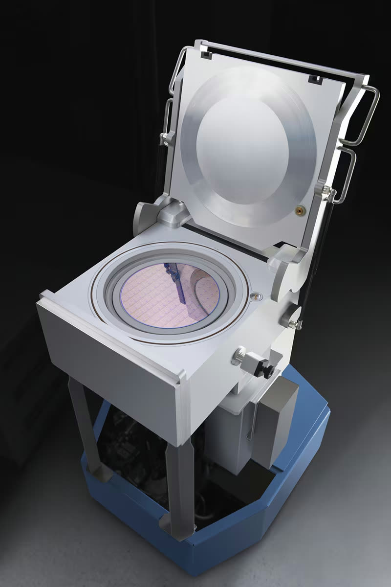
The fixture used to position the camera.
Software
The machine vision workflow used to evaluate the captured images.
Fixture Design
The fixture had to position the camera repeatably across several chamber variants while maintaining consistent image geometry and lighting. I designed the fixture in Autodesk Inventor with:
- Self-locking mechanismLocks automatically when the camera is rotated onto each pin position. Locking sensitivity and play are adjustable.
- IndexingMounts to several different chamber geometries.
- Controlled lightingLighting and shading kept consistent between images.
- Snap-on camera mountA snap-on fit for the camera mount.
- Ergonomic gripsGrips and handles that also house the required cables.
- Error-proofingFeatures that prevent incorrect installation.
I performed tolerance analysis across the fixture stack to verify fit between moving parts and confirm that camera positioning remained within the required range across all chamber variants.
Manufacturing
I 3D printed the fixture in cleanroom-safe PLA, with heat-set inserts in the printed parts for the fasteners. No printer available was large enough to print the fixture in one piece, so I split it into four parts.
Printing in four parts
Each part was printed individually, then post-processed until the dovetail joints fit.
Dovetail joints
The parts are held together by the dovetails alone: mechanical friction, no adhesive. Assembled, the four-piece fixture is rigid and has no play.
- Material
- Cleanroom-safe PLA
- Fasteners
- Heat-set inserts
- Printed parts
- 4, dovetail-jointed
Vision Model
A large collection of lift pin images was collected in the cleanroom, annotated, and used to train the model. I developed a two-stage machine vision workflow in Neuro-T.
Input
Full image
Captured through the fixture.
Stage 1
Object detection
Locates the lift pins in the full image.
Stage 2
Classification
Each detected pin is classified as pass or fail based on its alignment.
Why two stages
Separating detection and classification reduced unrelated image content during classification and made errors easier to diagnose.
Borderline cases
Because a false pass could allow a misaligned pin to damage the heater, the inspection approach was intentionally conservative when evaluating borderline cases.
Documentation and Release
I created the engineering drawings and bill of materials, ordered components from suppliers, and completed the Teamcenter release documentation for the fixture. This allowed the design to move beyond a prototype and into a documented configuration that could be fabricated, procured, and maintained.
1
Engineering drawings
2
Bill of materials
3
Supplier orders
4
Teamcenter release
Result
Developed an automated lift-pin alignment inspection system for several Metal Deposition chamber variants, combining a repeatable mechanical camera fixture with a two-stage machine vision workflow and digital inspection traceability.
Before the end of my internship, another process group asked to adapt the fixture design for their own defect detection application.