Background
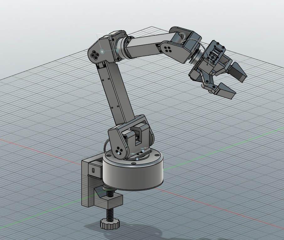
The goal of the project was a controller board for the 6-DOF robotic arm: one board that connects the PC over USB to the servos' half-duplex serial bus at 1 Mbps and distributes 12 V to six servo ports, mounted in a bay in the arm's base. It replaces an off-the-shelf servo bus adapter and separate power wiring. Revision 0.4 is released for fabrication with every part assembled by the manufacturer. It has not been fabricated yet.
Design Requirements
- USB linkUSB-C connection to the PC.
- Servo busHalf-duplex TTL serial bus at 1 Mbps, where the PC does not receive its own transmitted packets.
- Servo portsSix 3-pin ports: 1 GND, 2 +12 V, 3 DATA.
- Power12 V at up to 8.4 A worst-case arm hold, fused, reverse-polarity protected and switched.
- Mounting96 × 40 mm, mounted component side down on four M3 bosses in the base bay.
- AssemblyEvery part assembled by the manufacturer, through-hole connectors included.
Schematic
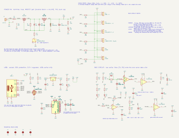
- USB to serialCH343G, rated to 6 Mbps; chosen over the CH340C because the manufacturer's datasheet directs 1 Mbps one-way traffic to the CH343. USBLC6-2SC6 ESD protection on the USB lines, 5.1 kΩ CC resistors, XC6206 3.3 V regulator.
- Half-duplex busAn SN74LVC1G126 drives the shared data line and an SN74LVC1G125 gates the receive path. One transmit-enable net drives both, in opposite senses. An SN74LVC1G14 generates it from TX with a timed RC (2.2 kΩ, 100 pF C0G, BAT54WS), so the PC does not receive its own packets.
- ReceiveMCP6561 comparator at a 1.5 V threshold with hysteresis; 33 Ω series resistor per port; bidirectional ESD diode on the data line.
- 12 V path12 A Littelfuse 451 SMD fuse (the 451 series is derated to 75 % for continuous use; worst-case hold is 8.4 A). Two AOD403 P-channel MOSFETs for reverse-polarity blocking and on/off switching with a 10 V gate zener, an SMBJ15CA TVS and a 1000 µF bulk capacitor.
Layout
2 layers, 1.6 mm FR-4, 1 oz copper.
Narrowest 12 V copper, rated 9.9 A for a 10 °C rise (IPC-2221).
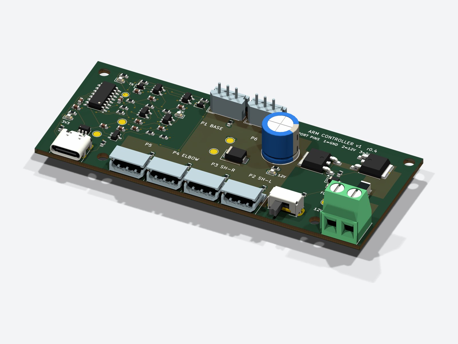
Placed parts, all assembled by the manufacturer.

- Power copperPower nets as copper pours. The narrowest 12 V section, measured from the routed board, is 7.1 mm of 1 oz copper. No vias in the current path.
- Signal routingSignal nets routed by a Python autorouter over an unbroken bottom ground plane.
- ConnectorsUSB-C, four servo ports, the switch and the 12 V terminal on one long edge.
- ToolsSchematic and layout generated from Python scripts in KiCad 10, with symbols and footprints from the KiCad libraries.
Verification and Manufacturing
ERC and DRC violations, DRC with schematic parity.
Diodes moved to equivalent parts without per-part assembly fees.
Quote for 5 boards with 2 assembled.
- Design checksEvery semiconductor pinout and every polar part checked against its datasheet; 0 unconnected pads.
- FitBoard STEP placed in the Fusion 360 arm assembly and collision-checked in the base.
- Revision 0.3 to 0.4The blade-fuse holder became an SMD fuse and an unused fallback header was removed, so the manufacturer assembles every part.
- Assembly filesChecked on JLCPCB's live quote and placement viewer: corrected the BOM format, an out-of-stock connector, through-hole part centroids and per-part rotations.
- Part costThe 13 fee-carrying parts surveyed against JLCPCB's basic and preferred libraries; four diodes moved to equivalent preferred parts.
Result
A two-layer controller board released for fabrication: ERC and DRC clean with schematic parity, fit-checked in the arm's CAD, and assembly files checked in the manufacturer's placement viewer, with the assembled-board quote reduced from $82.28 to $66.55.
Next Steps
- FabricationFabrication and assembly at JLCPCB.
- Bring-upBefore the arm: pin 1 checked with a meter before any servo is connected, the data line on a scope at 1 Mbps, the 12 V rail during a hard stop, and port temperature under load.